
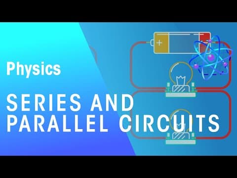
This blog post explores the fundamental differences between series and parallel circuits, detailing how voltage, current, and resistance behave in each configuration, along with practical examples and calculations.
Electricity is a fundamental aspect of modern life, and understanding how electrical circuits work is essential for anyone interested in physics or engineering. This post will delve into the two main types of electrical circuits: series and parallel circuits. We will explore their characteristics, how they function, and the calculations involved in analyzing them.
There are two primary types of electrical circuits:
In a series circuit, components are connected end to end, forming a single loop for the current to flow through. This configuration means that the same current flows through each component. A key characteristic of series circuits is that the total voltage from the power supply is divided among the components.
For example, if you have a circuit with a battery and two bulbs connected in series, the voltage provided by the battery is shared between the two bulbs. If the battery provides 1.5 volts, each bulb will receive a portion of that voltage, depending on their resistance.
In contrast, parallel circuits connect components side by side. This arrangement allows the current to divide, with some flowing through one path and the rest through another. In a parallel circuit, the voltage across each component remains the same, equal to the voltage of the power supply.
For instance, if two bulbs are connected in parallel to a 1.5-volt battery, each bulb receives the full 1.5 volts. The total current flowing through the circuit is the sum of the currents through each individual component.
To understand how series and parallel circuits operate, it is essential to grasp a few key concepts:
Voltage is a measure of the electrical push that the battery provides to the electrons. It is quantified in joules per coulomb (volts). A voltmeter measures this voltage and is always connected in parallel to the component being measured.
Current refers to the flow of negatively charged electrons in a circuit, analogous to water flowing through a pipe. It is measured in coulombs per second (amps) using an ammeter, which must be connected in series with the circuit.
Resistance is the opposition to current flow within an electrical circuit, measured in ohms (Ω). Higher resistance means it is more difficult for current to flow. A useful analogy is to think of voltage as the force pushing the current and resistance as a narrowing pipe that restricts flow.
In a series circuit:
For example, if two resistors of 3 ohms each are connected in series, the total resistance would be:
Total Resistance = 3Ω + 3Ω = 6Ω
In a parallel circuit:
For example, if two resistors of 3 ohms each are connected in parallel, the total resistance can be calculated using the formula:
1/R = 1/R1 + 1/R2
1/R = 1/3 + 1/3
1/R = 2/3
R = 3/2 = 1.5Ω
Let’s apply these concepts to a practical scenario. If a circuit has four cells providing a potential difference of 1.5 volts each, the total potential difference would be:
Total Voltage = 4 cells × 1.5V = 6V
If the current through a lamp is measured at 0.20 amps and through a resistor at 0.10 amps, the readings on the ammeter would reflect the total current flowing through the circuit.
Understanding the differences between series and parallel circuits is crucial for anyone studying electricity. By grasping how voltage, current, and resistance behave in each configuration, you can effectively analyze and design electrical circuits. Whether you are a student, a hobbyist, or a professional, these principles will serve as the foundation for your exploration of electrical systems.