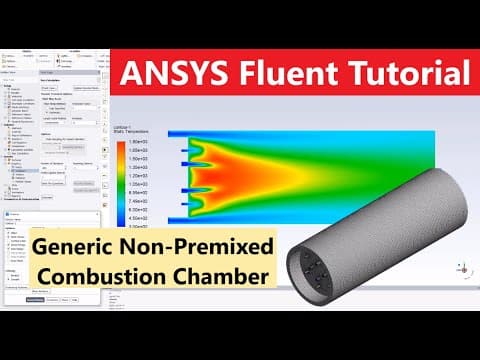
In this tutorial, we will explore the process of modeling a combustion chamber with non-premixed combustion of methane using ANSYS Fluent 2019. The focus will be on the k-epsilon viscous flow model, which is essential for accurately simulating the combustion process.
Combustion Chamber Specifications
The combustion chamber we will model has the following specifications:
- Diameter: 700 millimeters
- Length: 2000 millimeters
- Extrude Cut: 150 millimeters on the left face with an inner diameter of 600 millimeters
- Fuel Injectors: 6 injectors with a diameter of 20 millimeters, evenly spaced
- Air Injectors: 4 secondary air injectors with a diameter of 35 millimeters
- Pressure Outlet: Located downstream
Geometry Creation in Design Modeler
Step 1: Setting Up the Geometry
- Open the Workbench and drag the geometry into the project schematic.
- Open a new design modeler geometry and select the XY plane.
- Set the coordinate units to millimeters.
- Sketch a circle from the origin with a diameter of 700 millimeters.
- Use the extrude command to set the length to 2000 millimeters, creating a solid shape.
Step 2: Creating the Extrude Cut
- Transform the plane to offset Z by 2000 millimeters.
- Create a circle with a diameter of 600 millimeters and extrude cut it by 150 millimeters in the opposite direction.
Step 3: Adding Injectors
- Transform the plane again to create the injector face.
- Sketch circles for the fuel injectors (20 millimeters diameter, 200 millimeters vertical distance) and extrude them by 50 millimeters.
- Use the circular pattern tool to create 6 copies of the fuel injectors.
- Repeat the process for the air injectors (35 millimeters diameter, 100 millimeters vertical distance) and extrude them similarly.
Step 4: Finalizing the Geometry
- Use the boolean command to imprint the injector faces onto the combustion chamber.
- Name the faces for boundary conditions: primary air inlet, fuel injectors, outlet, and secondary air.
Meshing the Geometry
- Insert the method for meshing by selecting multi-zone with hexa meshing.
- Set the body sizing of the injectors to an element size of 1e-2 meters for a fine mesh.
- Generate the mesh and ensure it is fine enough for accurate results.
Setting Up the Simulation in Fluent
Step 1: Defining the Model
- Open the mesh in Fluent and set the physics preference to CFD Fluent.
- Define the models: energy equation, turbulence model (k-epsilon), radiation effects, and species transport model.
- Set the initial temperature to around 2000 degrees Celsius.
Step 2: Boundary Conditions
- Set the boundary conditions for the fuel injectors, primary air, and secondary air:
- Fuel Injectors: Mass flow inlet with a calculated mass flow rate of 7e-4 kg/s.
- Primary Air: 75% of total air mass flow, set as mass flow inlet.
- Secondary Air: 25% of total air mass flow, also set as mass flow inlet.
- Set the walls as adiabatic with no heat flux.
Step 3: Running the Simulation
- Start the hybrid initialization and run the solution for 300 iterations.
- Monitor the residuals to ensure convergence.
Analyzing the Results
- After the simulation completes, check the contours of temperature to visualize combustion.
- Analyze the mass fraction contours of O2 and OH to assess combustion efficiency and flame prediction.
- Observe the mixing of primary and secondary air with the fuel.
Conclusion
This tutorial has provided a detailed guide on modeling a non-premixed combustion chamber in ANSYS Fluent. By following these steps, you can effectively simulate combustion processes and analyze the results for various applications. Thank you for following along, and happy modeling!