
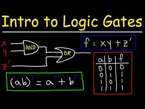
This article provides an in-depth exploration of logic gates, including their definitions, truth tables, and circuit representations. It covers buffer gates, NOT gates, AND gates, OR gates, NAND gates, and NOR gates, explaining their functions and how they relate to binary numbers and Boolean algebra.
Logic gates are fundamental building blocks in digital circuits, enabling the processing of binary information. This article delves into the various types of logic gates, their functions, and how they are represented in circuits.
Binary numbers are the foundation of digital electronics, consisting of only two digits: 0 and 1. In the context of circuits:
When dealing with voltage, an off state typically represents 0 volts, while an on state usually represents 5 volts or another positive voltage.
The buffer gate is a simple logic gate that outputs the same value as its input. Its symbol resembles a triangle pointing to the right.
| Input (A) | Output (A) |
|---|---|
| 0 | 0 |
| 1 | 1 |
The buffer gate can be represented using an NPN transistor. When a voltage is applied to the base of the transistor, it allows current to flow from the collector to the emitter, turning on an LED as the output. If no voltage is applied, the LED remains off.
The NOT gate, also known as an inverter, outputs the opposite value of its input. Its symbol looks similar to a buffer gate but includes a circle at the output.
| Input (A) | Output (A') |
|---|---|
| 0 | 1 |
| 1 | 0 |
In a NOT gate circuit, the LED is connected across the collector and emitter of the transistor. When the input is on (1), the LED is off (0), and vice versa.
The AND gate outputs a high value only when all its inputs are high. Its symbol is a flat-ended shape.
| Input A | Input B | Output (A AND B) |
|---|---|---|
| 0 | 0 | 0 |
| 0 | 1 | 0 |
| 1 | 0 | 0 |
| 1 | 1 | 1 |
An AND gate requires two transistors connected in series. The LED will only light up when both transistors are on.
The OR gate outputs a high value if at least one of its inputs is high. Its symbol resembles a curved shape.
| Input A | Input B | Output (A OR B) |
|---|---|---|
| 0 | 0 | 0 |
| 0 | 1 | 1 |
| 1 | 0 | 1 |
| 1 | 1 | 1 |
In an OR gate circuit, two transistors are connected in parallel. The LED will light up if either transistor is on.
The NAND gate is the complement of the AND gate, outputting a low value only when all inputs are high.
| Input A | Input B | Output (A NAND B) |
|---|---|---|
| 0 | 0 | 1 |
| 0 | 1 | 1 |
| 1 | 0 | 1 |
| 1 | 1 | 0 |
A NAND gate can be constructed using an AND gate followed by a NOT gate. The output is the complement of the AND gate's output.
The NOR gate is the complement of the OR gate, outputting a low value if at least one input is high.
| Input A | Input B | Output (A NOR B) |
|---|---|---|
| 0 | 0 | 1 |
| 0 | 1 | 0 |
| 1 | 0 | 0 |
| 1 | 1 | 0 |
Similar to the NAND gate, a NOR gate can be created by combining an OR gate with a NOT gate.
Logic gates are essential for building complex digital circuits. Understanding their functions, truth tables, and circuit representations is crucial for anyone studying electronics or computer science. This guide provides a foundational overview of the most common logic gates, including buffer, NOT, AND, OR, NAND, and NOR gates, and their applications in digital logic design.